Electromagnetic Brake Motors
5IK100VA-ESM
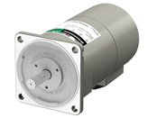
Motor
| Product Classification | Product Name | List Price | Shipping Date |
|---|---|---|---|
| Motor | 5IK100VA-ESM | Rs. 20,267 | 30 Working Days (Dispatch) |
Included
- Motor: None
Specifications
Characteristics
Starting and Braking Characteristics (Reference values)
Dimensions
Motor
Data Download
Other Specifications
General Specifications
| Item | Specifications |
|---|---|
| Insulation Resistance | 100 MΩ or more when a 500 VDC megger is applied between the windings and the case after continuous operation under normal ambient temperature and humidity. |
| Dielectric Strength | No abnormality is observed when 1.5 kVAC at 50 Hz or 60 Hz applied between the coils and case for 1 minute after continuous operation under normal ambient temperature and humidity. |
| Temperature Rise | A gearhead or equivalent heat sink* is connected to the motor, and the winding temperature rise is measured at 80 °C max. using the resistance change method after rated load continuous operation under normal ambient temperature and humidity. |
| Thermal Class | 130 (B) |
| Operating Ambient Temperature | -10~+40 °C (Non-freezing) |
| Operating Ambient Humidity | 85 % max. (Non-condensing) |
| Degree of Protection |
Terminal Box Type: IP66 (excluding mounting surface of round shaft type) Lead Wire Type: IP20 Cable Type: IP40 |
Note
- No built-in overheat protection device (thermal protector).
When there is an overload or the output shaft is locked, use the electromagnetic switch and the inverter's electronic thermal function
to prevent motor burnout.
- *Heat sink size (Material: aluminum)
| Motor Type (Output power) | Size (mm) | Thickness (mm) |
|---|---|---|
| 30 W Type | 135 × 135 | 5 |
| 40 W Type | 165 × 165 | |
| 60 W Type | 200 × 200 | |
| 100 W Type | ||
| 200 W Type | 250 × 250 | 6 |
Permissible Radial Load and Permissible Axial Load
Parallel Shaft Combination Type
| Product Name | Gear Ratio | Permissible Radial Load N | Permissible Axial Load N | |
|---|---|---|---|---|
| 10 mm From the End of the Output Shaft | 20 mm From the End of the Output Shaft | |||
| 4IK30 | 5~25 | 300 | 350 | 100 |
| 30~3600 | 450 | 550 | ||
| 5IK40 | 5~9 | 400 | 500 | 150 |
| 12.5~18 | 450 | 600 | ||
| 25~3000 | 500 | 700 | ||
| 5IK60 | 5~9 | 400 | 500 | 150 |
| 12.5~18 | 450 | 600 | ||
| 25~300 | 500 | 700 | ||
| 5IK100 | 5~9 | 400 | 500 | 150 |
| 12.5~18 | 450 | 600 | ||
| 25~180 | 500 | 700 | ||
| 7IK200 | 5~20 | 700 | 860 | 200 |
| 30~100 | 1400 | 1700 | 400 | |
Round Shaft Type
| Product Name | Permissible Radial Load N | Permissible Axial Load N | ||
|---|---|---|---|---|
| 10 mm From the End of the Output Shaft | 20 mm From the End of the Output Shaft | Induction Motor Reversible Motor |
Electromagnetic Brake Motor | |
| 4IK30 | 90 | 140 | 15 | - |
| 5IK40 | 140 | 200 | 20 | - |
| 5IK60 | 240 | 270 | 20 | 14 |
| 5IK100 | 240 | 270 | 20 | 17 |
| 7IK200 | 320 | 350 | 30 | - |
Recommended Electromagnetic Switch
Always connect an electromagnetic switch when connecting the motor power supply.
Use an electromagnetic switch from the following product list, or an equivalent.
Set the rated current of the motor for the stabilized current of the thermal relay.
For the rated current of the motor, check the specifications for each product.
Fuji Electric FA Components & Systems Co., Ltd.
| Product Name | Part Number | |
|---|---|---|
| Parallel Shaft Combination Type, Round Shaft Type |
Right-Angle Hollow Shaft Hypoid Gearhead | |
|
4IK30
5IK40 |
4IK30VKJS, 4IK30VKES
5IK40VKJS, 5IK40VKES |
SC11AAN-□10TD |
| 5IK60 | - | SC11AAN-□10TF |
| 5IK100 | 5IK100VKJS | SC11AAN-□10TH |
| - | 5IK100VKES | SC11AAN-□10TG |
| 7IK200 Voltage 200-240 V | 7IK200 Voltage 200-240 V | SS11AAN-□10TK |
| 7IK200 Voltage 380-415 V | 7IK200 Voltage 380-415 V | SS11AAN-□10TH |
- *A letter indicating the winding code is specified where the box □ is located in the part number.
Use a product with the winding code that corresponds with the rated voltage of the motor.
| Rated Voltage | Winding Code | |
|---|---|---|
| 50 Hz | 60 Hz | |
| 200 V | 200-220 V | 2 |
| 200-220 V | 220-240 V | M |
| 220-240 V | 240-260 V | P |
| 346-380 V | 380-420 V | S |
| 380-400 V | 400-440 V | 4 |
| 415-440 V | 440-480 V | T |
Manufactured by Mitsubishi Electric Corporation
| Product Name | Part Number | |
|---|---|---|
| Parallel Shaft Combination Type, Round Shaft Type |
Right-Angle Hollow Shaft Hypoid Gearhead | |
|
4IK30
5IK40 |
4IK30VKJS, 4IK30VKES
5IK40VKJS, 5IK40VKES |
MSO-T10 0.24A 200V AC200V |
| 5IK60 | - | MSO-T10 0.35 A 200 V AC200 V |
| 5IK100 | 5IK100VKJS, 5IK100VKES | MSO-T10 0.5 A 200 V AC200 V |
| 7IK200 Voltage 200-240 V | 7IK200 Voltage 200-240 V | MSO-T10 0.9 A 200 V AC200 V |
| 7IK200 Voltage 380-415 V | 7IK200 Voltage 380-415 V | MSO-T10 0.5 A 400 V AC400 V |
Usage with Inverter
When using in combination with an inverter, the setting frequency conditions of the inverter are as follows.
Refer to the operating manual for motor settings and precautions.
| Type | Product Name | Frequency |
|---|---|---|
| Right-Angle Hollow Shaft Hypoid Gearhead | 4IK30 | 100 Hz max. |
| 5IK40 | 80 Hz max. (60 Hz max. for gear ratio 10) | |
|
5IK100 7IK200 |
120 Hz max. | |
| Parallel Shaft Gearhead GV Gearhead Round Shaft Type |
4IK30
5IK40 5IK60 5IK100 7IK200 |
120 Hz max. |
Standards
Regulations and Standards Materials
Documents about compliance with regulations and standards can be downloaded from the "Data Download" tab on the product details page.
(The types of files available for download vary by product.)
Explanations of the Global Laws, Regulations and Standards can be found here.
Information about our compliance with safety standards for each of our product models can be found here.
Hazardous Substances
The product does not contain any substances (10 substances) exceeding the regulation values of the RoHS Directive (2011/65/EU, 2015/863/EU).
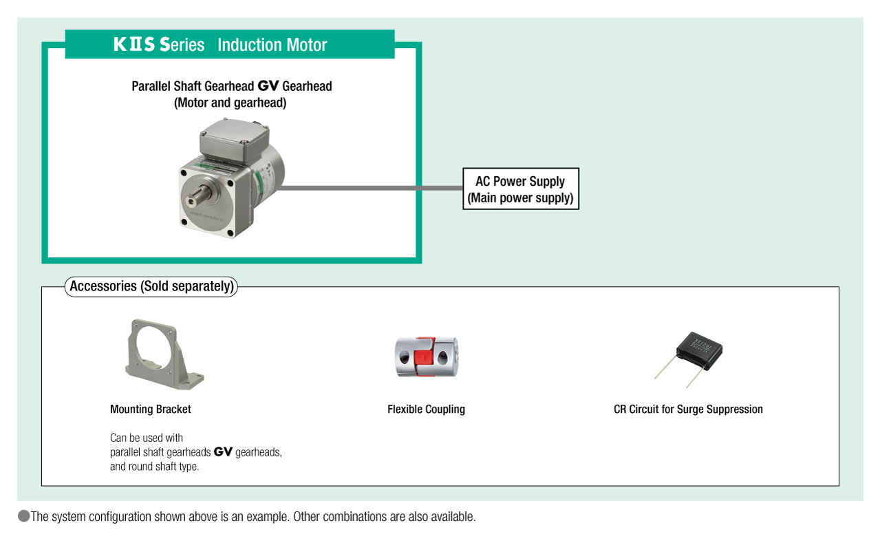
System Configuration