αSTEP
AR Series
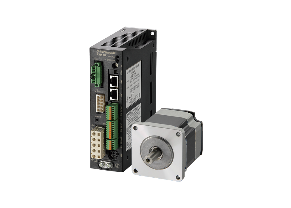
- Equipped with Resolver Sensor
- AC/DC Input
- Low Cost of Entry
Features | αSTEP AR Series
Hybrid Control for Easier Use and More Reliable Control
αSTEP is a stepper motor based motor with a unique control that hybridizes the advantages of open loop control and closed loop control. It constantly monitors the position of the motor while automatically switching between the 2 controls depending on circumstances.
Open Loop Control in Normal Operation is as Easy to Use as Stepper Motors.
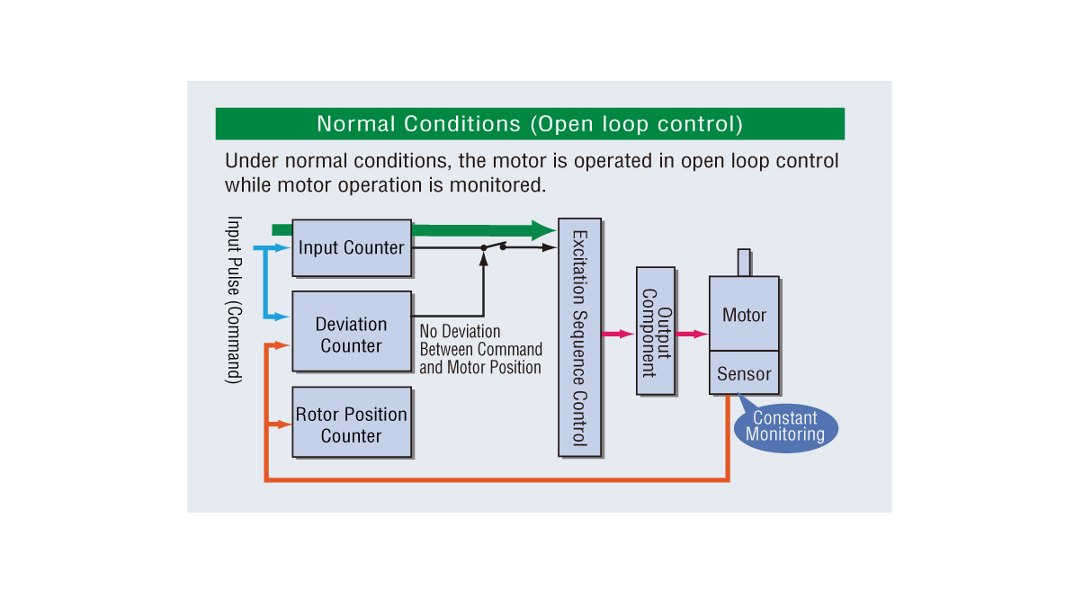
High Response
Short distances can be moved in a short period of time by utilizing the stepper motor’s high response. The motors can execute commands without lagging.
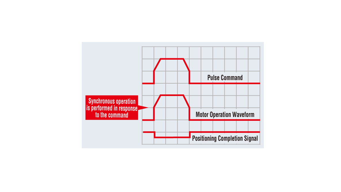
Holding the Stop Position without Hunting
During positioning, the motor stops with its own holding force without hunting. Because of this, it is ideal for applications where the low rigidity of the mechanism requires absence of vibration upon stopping.
Tuning-Free
Because it is normally operated with open loop control, positioning is still possible without gain adjustment even when the load fluctuates due to the use of a belt mechanism, cam, or chain drive, etc.
In Case of Overload, Closed Loop Control Provides More Reliable Operation.
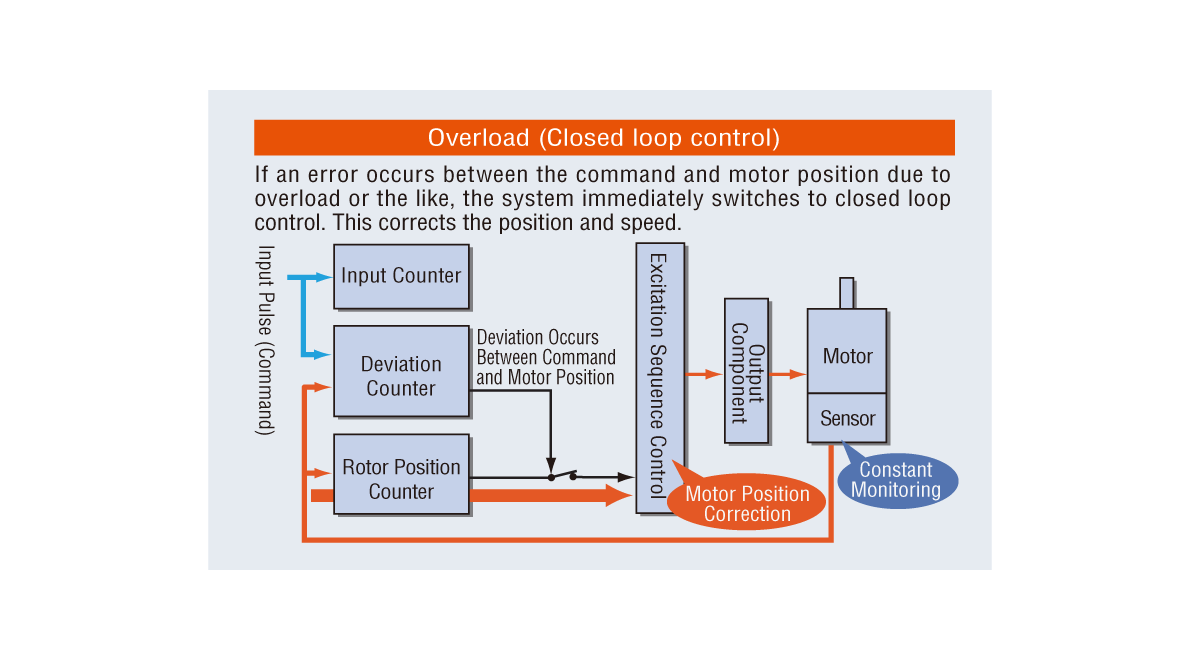
Continues Operation Even with Sudden Load Fluctuation and Sudden Acceleration
It operates synchronously with commands using open loop control during normal conditions. When overload occurs, it switches immediately to closed loop control to correct the position.
Alarm Signal Output in Case of Abnormality
If an overload is applied continuously, an alarm signal is output. When the positioning is complete, an END signal is output. This ensures the same level of reliability as a servo motor.
Smooth Operation Even at Low Speed
The standard microstep drive and smooth drive functions * reduce vibration at low speeds for smooth operation.
- *The smooth drive function automatically microsteps based on the same traveling amount and traveling speed used in the full step mode, without changing the pulse input settings.
Reduced Motor Heat Generation and Continuous Operation Possible through High Efficiency
Significantly Reduced Heat Generation
-
Temperature Distribution by Thermography
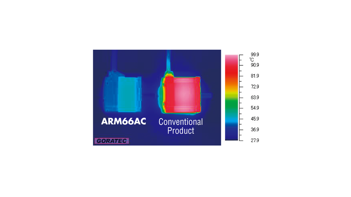
This is an example of operation under the same conditions. -
Motor Surface Temperature during Operation Under the Same Conditions

Power Consumption Reduction via Energy Savings
-
AC Input
Power consumption 45% less than conventional models (compared to Oriental Motor)
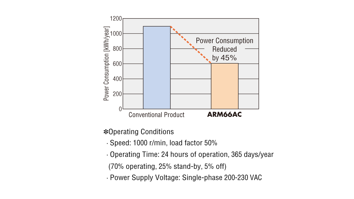
-
DC Input
Power consumption 35% less than conventional models (compared to Oriental Motor)
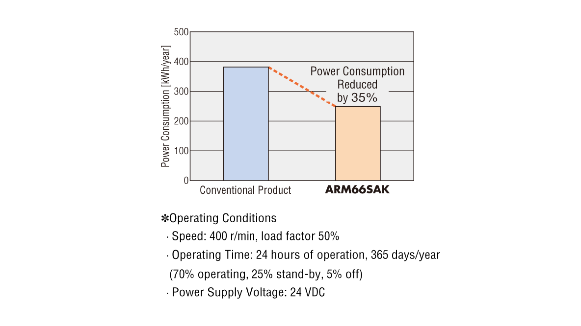
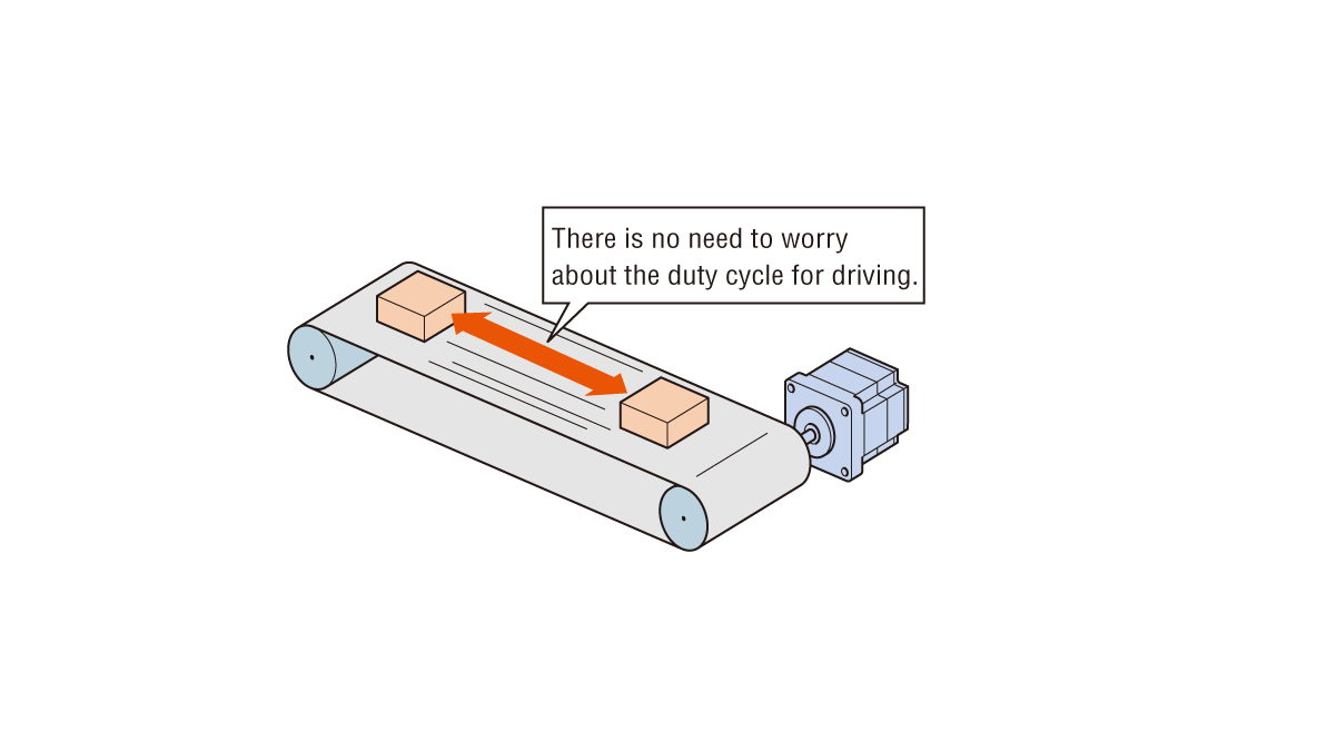
Continuous Operation (High frequency operation)
Can be operated at high frequency. The motor can be driven continuously.
Note
For continuous operation, a heat sink equivalent to an aluminum plate of the following size is required.
- AC input: 250 × 250 mm, 6 mm thickness
- DC input: 100 × 100 mm, 6 mm thickness
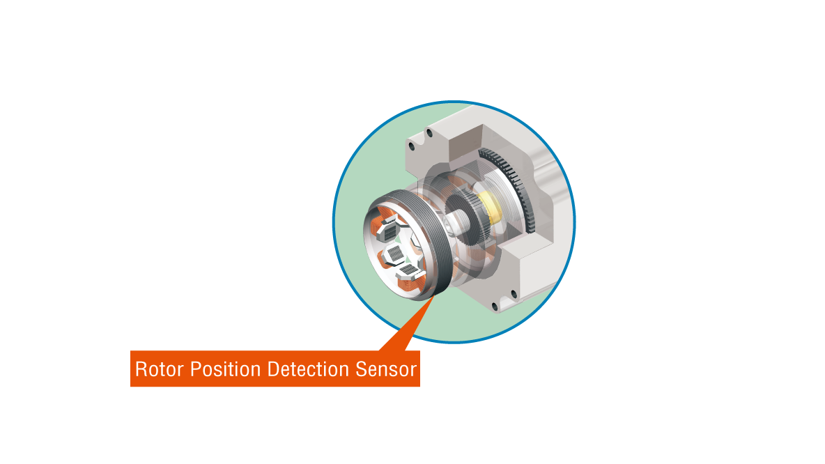
Rotor Position Detection Sensor (Resolver) Equipped
The rotor position detection sensor detects rotor position information by using changes in inductance caused by changes in the clearance distance between the small teeth of the sensor rotor and the small teeth of the stator.
Reference Output Power for Stepper Motor (AC input only)
The output power (W) of the AC servo motor is indicated as "rated output power" when it is running at "rated speed."
On the other hand, as stepper motors, with their characteristic high precision positioning and high torque at medium and low speeds, have no "rated speed," no "rated output power" is given.
The following page shows for reference how much torque of the AR Series motor corresponds to the rated torque of what W of servo motors’ rated torque.
Pursuing Ease of Start-up, Control, and Maintenance
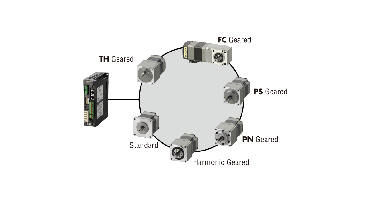
A Single Driver to Support a Variety of Motors
Various types of motors, such as the standard type and the geared type, can be connected to a single driver. Since there is no need to change the driver model for each motor combination, maintenance support is simplified. The driver is also equipped with an automatic recognition function to identify the type of motor connected.
The rotor position detection sensor detects rotor position information by using changes in inductance caused by changes in the clearance distance between the small teeth of the sensor rotor and the small teeth of the stator.
Easy to Use with High Functionality
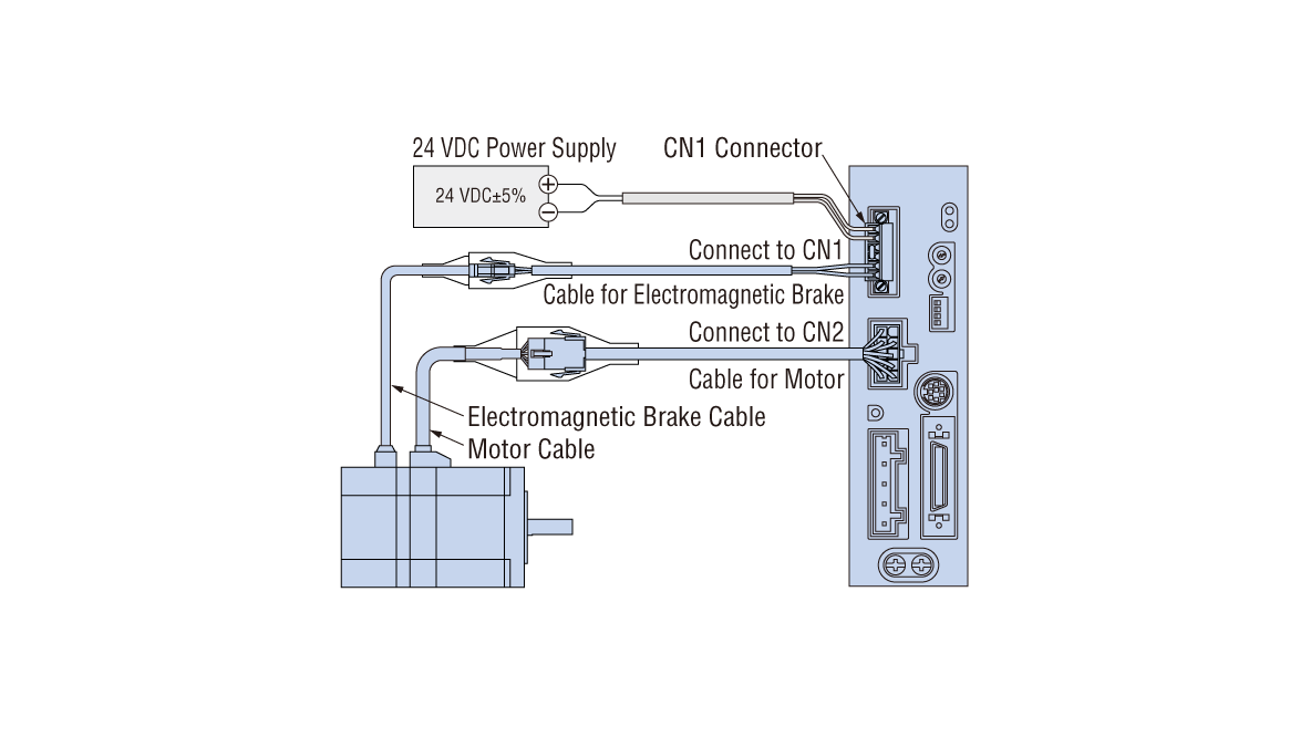
Automatic Electromagnetic Brake Control (Excluding DC input pulse input type)
The electromagnetic brake is released when the motor is excited (= the current ON input is turned ON), and activated to hold the load in position when the excitation is cut off (= the current ON input is turned OFF). It is not necessary to provide a separate brake control circuit.
Note
AC input pulse input type requires a separate 24 VDC power supply for electromagnetic brake control.
Separation of Main Power and Control Power
The control power-input terminals are provided separately from the main power terminals. Even if the main power supply is cut off due to an emergency stop, etc., the position can be detected, and the alarm contents can be checked as long as 24 VDC is applied to the control power supply terminal. The pulse input type allows for operation even with power supplied only from the main power supply.
Maximum Extension Distance between Motor and Driver is 30 m.
The motor and driver can be extended up to 30 m using a connection cable. Extension cables and flexible cables are also available.
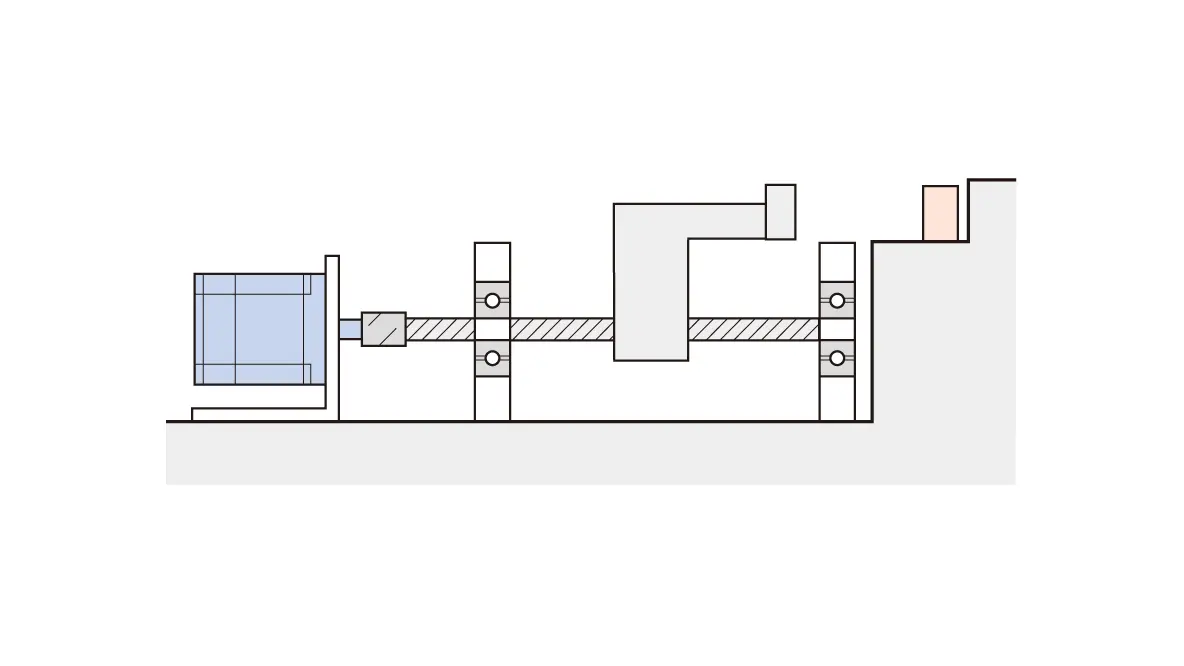
Push-Motion Operation
A force is continuously applied to the load. When contact is made with the load, the motor switches to push-motion operation status, and can pressurize at a constant torque.
Note
- The control module OPX-2A (sold separately) or MEXE02 support software is required to use push-motion operation.
- Do not perform push-motion operation using geared types. Doing so may damage the motor or gearhead.
Position Control in the Same Direction
The wrap function enables you to control positioning even in an application where positioning is repeated in the same direction.
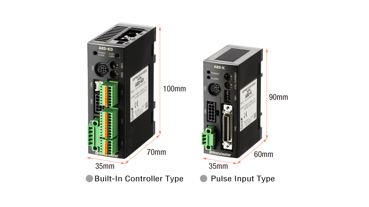
Compact Driver (DC input only)
This contributes to space saving for the control cabinet and equipment. Can be mounted directly on a DIN rail.
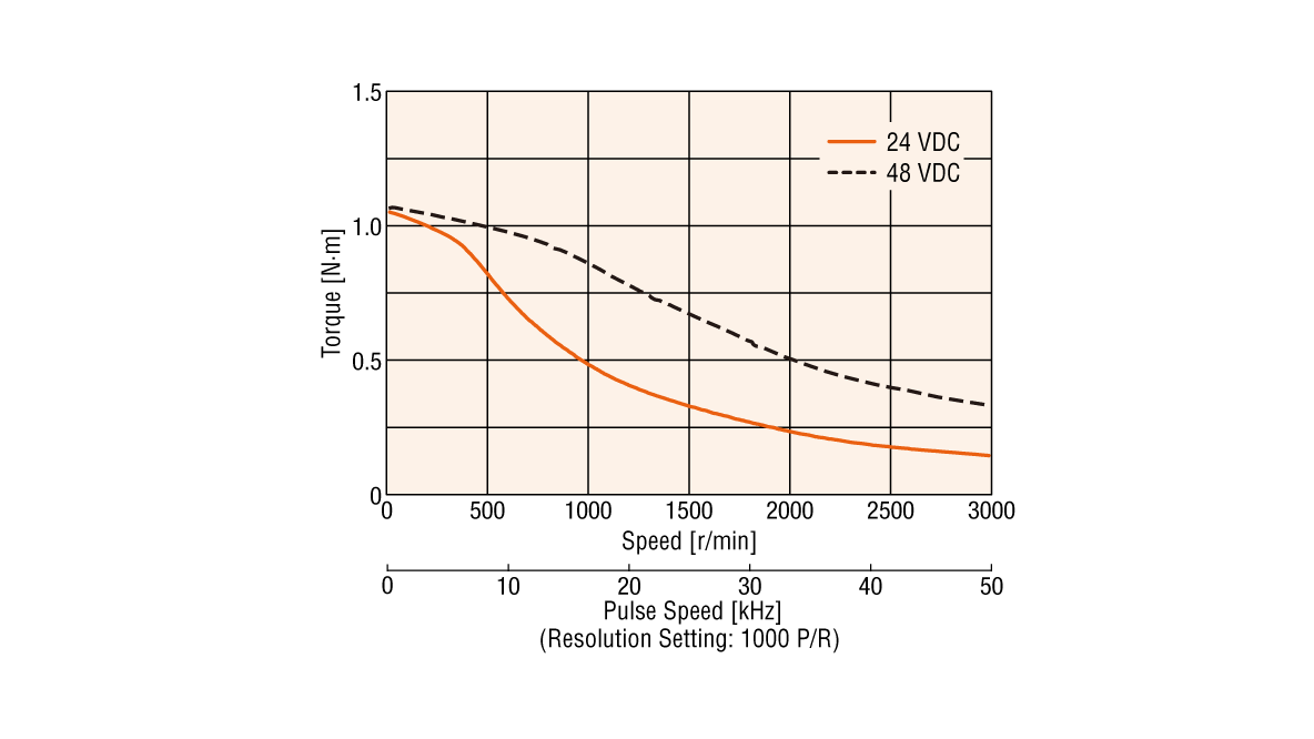
Compatible with 48 VDC
The motor runs on a 24 VDC or 48 VDC power supply. When used with 48 VDC, the torque is increased compared to 24 VDC. (20 mm and 28 mm frame sizes are for 24 VDC input only.)
A Stepper Motor with Advanced Characteristics; Easier to Use
-
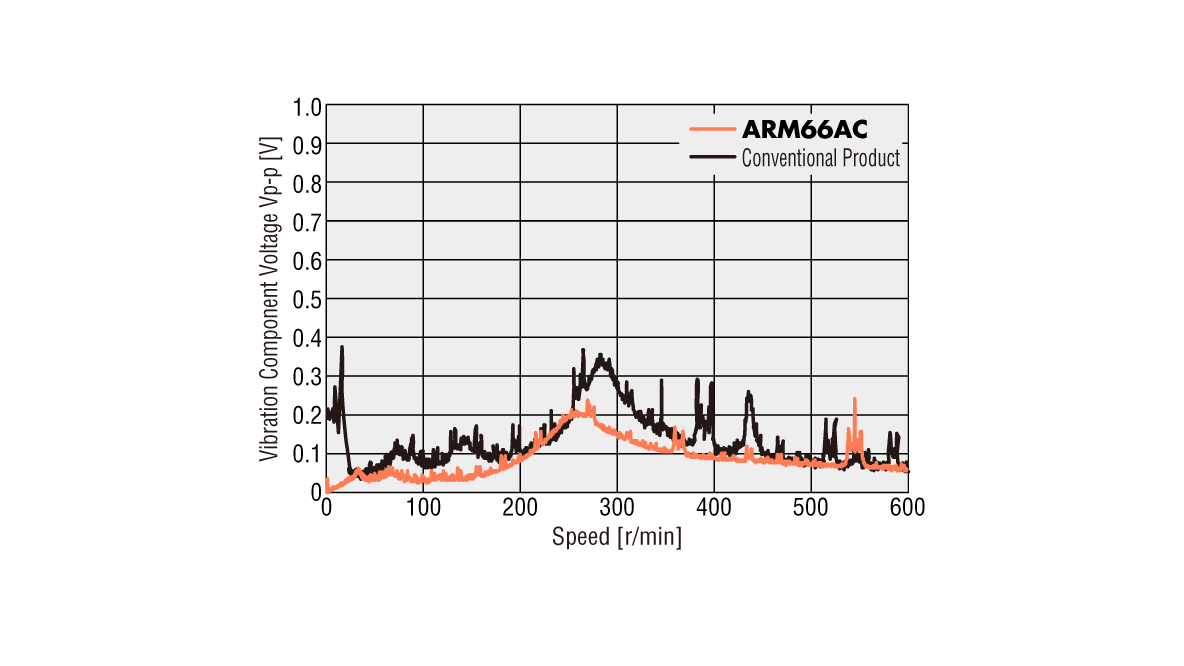
Low Vibration
In addition to the microstep drive system, a smooth drive function has been added to make operation smoother. Even without changing the pulse input setting, the microstep drive is automatically performed with the same travel amount and travel speed as with the full step.
-
Improved Angular Accuracy
The improved current control technology improves the stop position accuracy of the motor. More accurate positioning is possible.
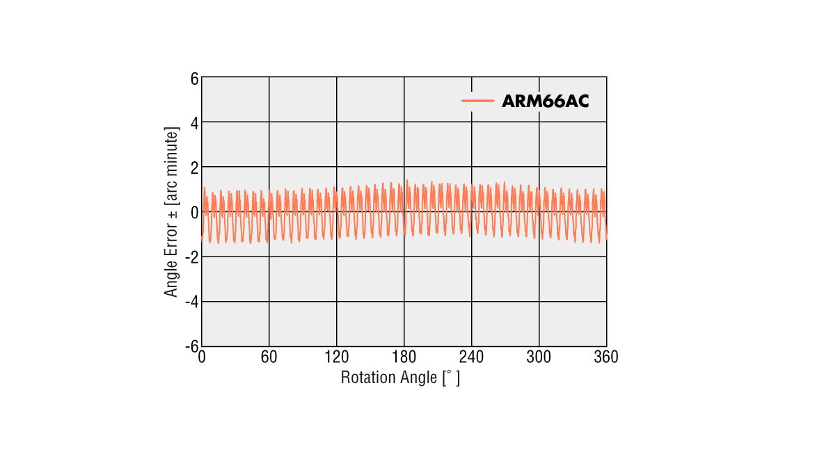
ARM66AC: ±3 min/Conventional product: ±5 min
Easy Setup, Easy Operation
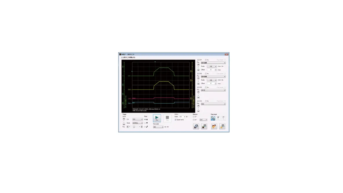
The MEXE02 support software supports users with anything from start-up to maintenance. In addition to setting and editing the operation data and various parameters with a computer, you can conduct teaching and monitor various statuses.
Waveform Monitoring
A wide range of monitoring functions are available to grasp the motor operation status and I/O status.
Supports Various Standards to Assist Equipment Design (AC input only).
Degree of Protection IP65*
The degree of protection of the motor is IP65*. This means that the enclosure prevents intrusion of dust that can otherwise inhibit normal operation. (*Excluding the motor mounting surface and connector part. IP20 for double shaft products.)
Complies with the "SEMI F47" Standard for Semiconductor Manufacturing Equipment.
These products comply with the SEMI Standard on power supply voltage drop, and accordingly can be used effectively in semiconductor manufacturing apparatuses. The product can be considered for use in semiconductor manufacturing equipment. However, be sure to evaluate the product on actual equipment.
Components Conforming to International Safety Standards
These products are recognized by UL/CSA standards and they also bear the CE Marking as a proof of conformance to the Low Voltage and EMC Directives.
2 Driver Types Available to Match the System Configuration

Built-in Controller Type
This type reduces the burden on the host PLC by setting the information necessary for motor operation to the driver. The data can be set using either the OPX-2A control module (sold separately), the MEXE02 support software, or RS-485 communication. The system configuration is simple in the case of multi-axis control.

Operation Types
In the built-in controller type, operation data such as operating speed and travel amount are set, and these operation data are selected for operation. There are 4 types of motor operations.
-
Group Send Function
This function allows multiple axes to be started simultaneously via Modbus (RTU) communication or industrial network. Multiple drivers can be grouped together, and when an operation command is sent to the master driver, all the drivers that belong to the same group as the master driver will operate simultaneously. In the case of Modbus (RTU) communication, the function simultaneously supports travel amount, speed change, and monitoring.
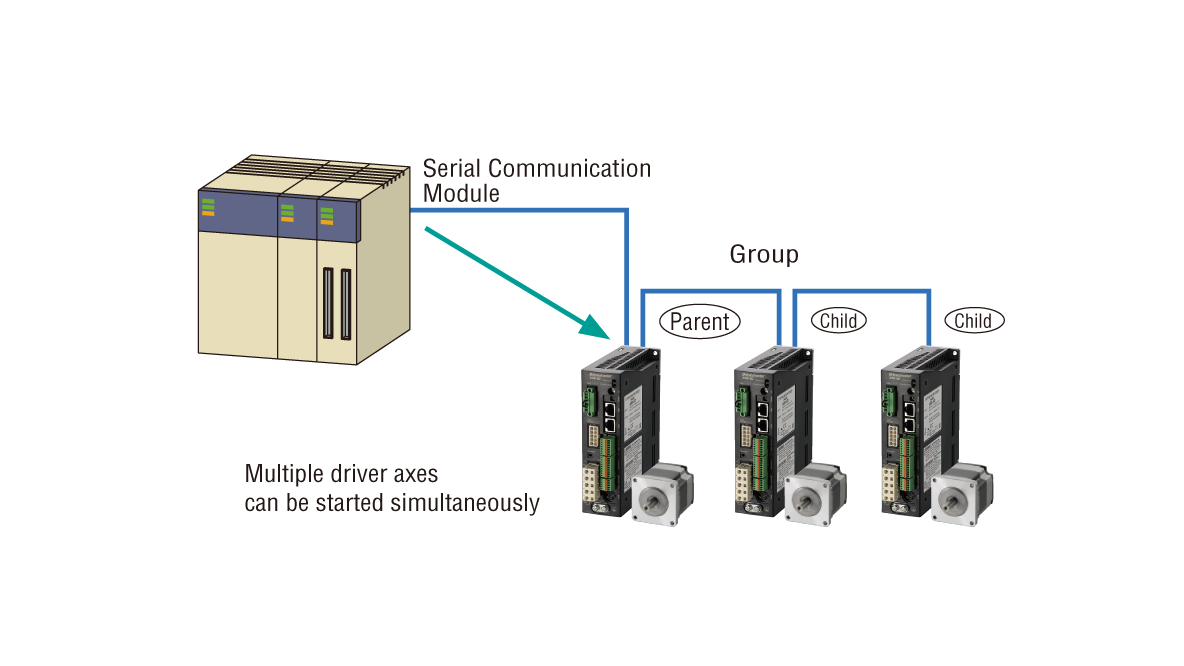
Example of Modbus (RTU) Communication Control -
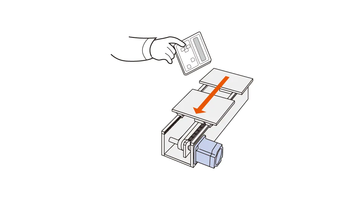
Teaching Function
Teaching can be done using the control module OPX-2A (Sold separately) or the MEXE02 support software. The table is moved to the target position, and the position data at that time is stored as positioning data.
Click here to download the MEXE02 support software
Example of Modbus (RTU) Communication Control
Control System Configuration for Built-in Controller Type
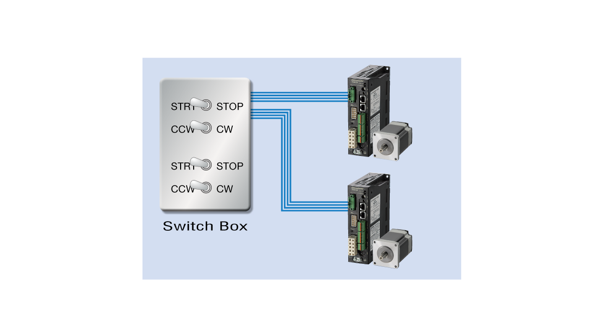
Switch Box Use Example – I/O Control Low-Cost Design
As operation data is set in the driver, the motor can be started and stopped by simply connecting it to a switch at hand. Easy to control without using a PLC.
PLC Use Example – I/O Control Low-Cost Design Space Saving Space Saving
When using PLC, an operation system can be configured by connecting directly to an I/O module. A positioning module is not necessary on the PLC side, saving space and simplifying the system.

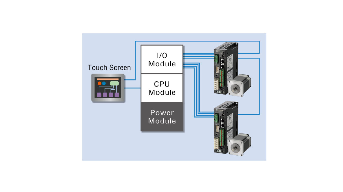
PLC and Touch Screen Usage Example – I/O Control Supporting a Wide Variety of Products and Small Lots
Normally, the motor is started and stopped with I/O. A touch screen using Modbus (RTU) communication is used to change settings, monitor operation data, and as an alarm display. When there is a lot of setup work, changes can be easily performed on the touch screen, and the burden of creating ladders is reduced.
Control via Modbus (RTU) / RS-485 Communication Wire-Saving Serial Communication Module Computer Control System Simplification
Operation data setting, parameter setting, and operation command input are performed via RS-485 communication. Up to 31 drivers can be connected to a single serial communication module, allowing simultaneous start of multiple axes. Supports Modbus (RTU) and can be connected to a touch screen, computer, etc.
Control via FA Network Wire-Saving Multi-Axis Control at Low Cost
By using a network converter (sold separately), CC-Link, MECHATROLINK or EtherCAT communication is possible. Operation data setting, parameter setting, and operation command input can be performed through either of these communications.
Pulse Input Type
The pulse input type operates by inputting pulse signals from the positioning module (pulse generator) to the driver. Parameter setting and monitoring can be performed using the control module (Sold separately) or MEXE02 support software.

Main Additional Functions Available with Extended Settings
Vacuum Type is Also Available
Positioning operation in a vacuum environment of 10-5 Pa is possible while maintaining the high reliability of closed loop control. The high efficiency motor and driver enable high-torque operation even in a vacuum with low heat radiation. By eliminating the use of a rotary feeder in the vacuum environment equipment, it contributes to the downsizing of the equipment.
Click here for details on Vacuum type
Narrow down Products
Download
Operating Manual
Support Software
Lineup and Related Information

Combining with Other Manufacturers' Products


