Driver for Stepper Motor
CMD2120P
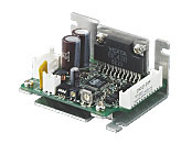
Control Circuit
This product is currently no longer available for sale
| Product Classification | Product Name | List Price | Shipping Date |
|---|---|---|---|
| Control Circuit | CMD2120P | Rs. 11,000 | Discontinued Product (31.3.2025 discontinued) |
Specifications
Data Download
Other Specifications
Circuit Specifications
| Input Signals | Input Mode | Photocoupler Input CW Pulse (pulse) Signal, CCW Pulse (Rotation direction) Signal: Input resistance 200 Ω, Input current 5~20 mA Photocoupler "ON": +3 ~ 5.25V Photocoupler "OFF": 0 ~ +1V (voltage between terminals) Output current off signal, step angle switching signal, and automatic current cutback release signal: Input resistance 3.3 kΩ Input current 1 mA (at 5 VDC)/8 mA (at 24 VDC) Photocoupler "ON": +4.5~26.4 V, Photocoupler "OFF": 0~+1 V (voltage between terminals) |
|---|---|---|
| CW Pulse Signal (Pulse signal) |
CW direction operation command pulse signal (operation command pulse signal when in 1-pulse input mode), negative logic pulse input Pulse width 5 μs min., rise/fall time 2 μs max., pulse duty 50 % max. When the pulse input is turned from "ON" to "OFF," the motor rotates 1 step. Maximum input pulse frequency 100 kHz (at 50 % pulse duty) |
|
| CCW Pulse Signal (Rotation direction signal) |
CCW direction movement command pulse signal (for 1-pulse input mode, rotation direction signal Photocoupler ON: CW, Photocoupler OFF: CCW) photocoupler "OFF": CCW) Negative logic pulse input Pulse width 5 μs min., rise/fall time 2 μs max., pulse duty 50 % max. When the pulse input is turned from "ON" to "OFF," the motor rotates 1 step. Maximum input pulse frequency 100 kHz (at 50 % pulse duty) |
|
| All Windings Off Signal | When the photocoupler is "ON," the output current to the motor is turned "OFF," and the motor shaft can be turned by external force. When the photocoupler is "OFF," output current to the motor is turned "ON." |
|
| Step Angle Select Input Signal | When the photocoupler is "ON," the motor operates at the basic step angle regardless of how the step angle setting switches are set. When the photocoupler is "OFF," operates at the step angle set by the step angle setting switch. |
|
| Automatic current cutback release signal |
When the photocoupler is "ON," the automatic current cutback function is canceled at motor standstill. When the photocoupler is "OFF," the automatic current cutback function will be activated at motor standstill (after approx. 100 ms). |
|
| Output Signals | Output Mode | Photocoupler and Open-Collector Output External Use Condition: 24 VDC max., 10 mA max. |
| Excitation Timing Signal |
This signal is output when the excitation sequence is step "0." (Photocoupler "ON") [For High-Torque Type and Standard Type] Example)
1.8°/step (number of divisions - 1): Output once every 4 pulses
0.45°/step (number of divisions - 4): Output once every 16 pulses [For High-Resolution Type] Example)
0.9°/step (number of divisions - 1): Output once every 4 pulses
0.225°/step (number of divisions - 4): Output once every 16 pulses [For SH Geared Type (Gear ratio: 18)] Example)
0.1°/step (number of divisions - 1): Output once every 4 pulses
0.025°/step (number of divisions - 4): Output once every 16 pulses |
|
| Function | Automatic current cutback, step angle switching, pulse input mode switching, all windings off, excitation timing | |
| Cooling Method | Natural cooling method | |
close