Development Case Studies
Battery-Free Multi-Rotation Absolute Encoder
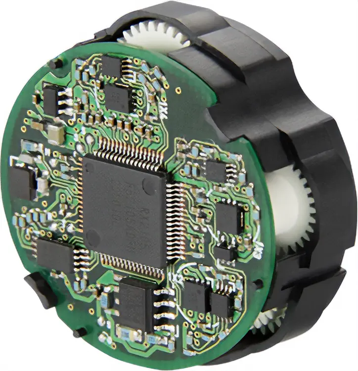
By employing high-precision resin parts and using magnetic sensors, we have successfully developed a compact, low-cost multi-rotation absolute encoder that does not require a battery.
1. Background
An absolute system is capable of retaining absolute position information even when the power supply is turned off. It does not require a return-to-home operation and can run immediately after the power supply is turned on, which shortens the takt time. Since it is not necessary to do return-to-home operations, home sensors and limit sensors are also not required, leading to cost-cutting and saving of wiring.
However, in cases where batteries are used, the maximum period of retaining position information after losing the main power supply is about 2 weeks even when the batteries are fully charged. Moreover, if the system is turned off for a long period of time, readjusting home position might be necessary when restoring information.
In addition, batteries have a limited lifespan, so regular maintenance and replacement are required. Because the position information is lost whenever the battery is disconnected, the home position of the equipment must be reset each time it is disconnected.
Such problems have led to the need for a multi-rotation absolute encoder that does not require a battery, and for that reason, a mechanical multi-rotation absolute encoder using a gear mechanism was invented. However, mechanical sensors are not only complex in structure, but also large in size and expensive.
Therefore, Oriental Motor worked on the development of a new mechanical multi-rotation absolute encoder that is both compact and inexpensive.
2. Principle and Structure
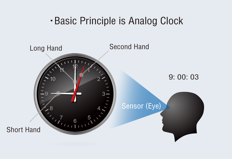
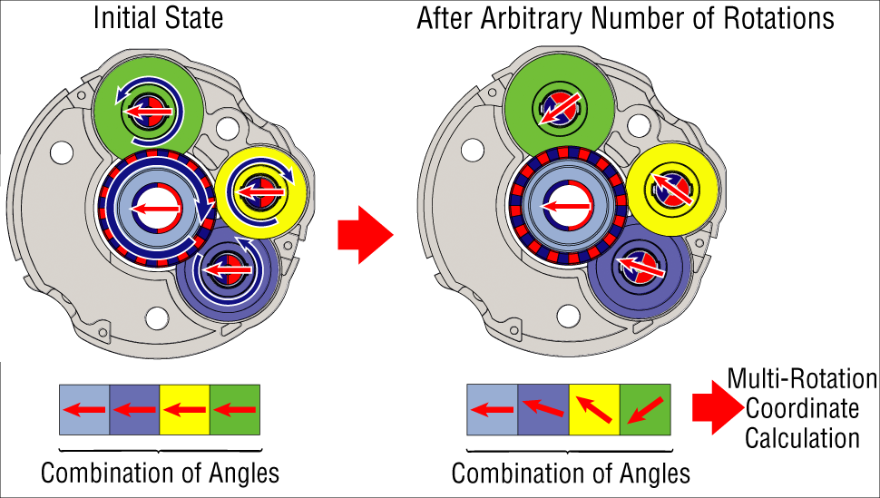
The position detection mechanism of the newly developed absolute encoder operates on a principle similar to the telling of time from the combination of angles (phase differences) of the hour hand, minute hand, and second hand of a clock. It is equipped with 4 gears that correspond to the hands of a clock, each of which the position is detected by a sensor and recognized as position information. Each gear pair has a tooth count difference, and therefore, the phase differences between the meshing gears change every time the motor shaft rotates. By utilizing the phase differences, which are caused by the ratio of tooth counts, the gear phase difference is detected in increments of 1 tooth (1 pitch), and based on the combination of these phase differences, the multi-rotation coordinate is calculated (see figure). The phase differences of all gears are designed to return to their initial states after rotating 1,800 times. This feature enables the detection of multi-rotation coordinates for up to 1,800 revolutions.


3. Examples of Commercialization
The newly developed sensor makes possible the construction of a multi-rotation absolute system that does not require batteries. This sensor is mounted on the "Hybrid Control System with αSTEP Absolute Encoder AZ Series" and is used in a wide range of equipment.
Applicable Products
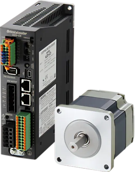
Hybrid Stepper Servo αSTEP Absolute Encoder Equipped AZ Series