


Home > Product Information > Stepping Motors >
AZ Series EtherNet™/IP Compatible > List of Product > AZM98MC-PS10+AZD-AEP+CC030VZFB
- Accessory
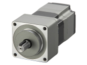
- Motor : Parallel Key
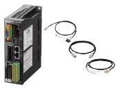
Control Circuit: Connector for the Main Power Supply and Regeneration Unit (CN4)、Connector for 24 VDC Power-Supply Input/Electromagnetic Brake Connection/Regeneration Unit Thermal Input/Power Cutoff Signal I/O(CN1)、I/O Signals Connector(CN7)、Connector wiring lever
Cable:Connection cable is 3m long. Flexible Cable types and other lengths are available. For details, please refer to the cable dimensions.
- Safety Standards
-


| Product Type | Product Name | Product Leadtime | Unit Price(INR) | |
|---|---|---|---|---|
| Motor | AZM98MC-PS10 | 25 Working Days (Dispatch) | 82,000 | |
| Control Circuit | AZD-AEP | 40 Working Days (Dispatch) | 52,267 | |
| Connection Cables | CC030VZFB | 25 Working Days (Dispatch) | 6,200 |
Delivery date depends on products qty. Product price only. Dispatch from Bangalore Headquarter. Please contact ORIENTAL MOTOR (INDIA) PVT.LTD.
●Production Information
Current product *Cables are available in flexible types and other lengths.
| Frame Size | 90mm |
|---|---|
| Type | PS Geared Type |
| Shaft Type | Single Shaft |
| Electromagnetic Brake | Equipped |
| Cable | 3m(Standard Cable) |
| Driver Type | EtherNet/IP Compatible Driver |
| Maximum Holding Torque | 20N・m |
| Rotor Inertia J | 1250×10^-7kg・m^2 |
| Backlash | 7arcmin (0.12°) |
| Speed Range | 0~300r/min |
| Gear Ratio | 10 |
| Resolution Setting: 1000 P/R | 0.036°/Pulse |
| Rated Torque | 20N・m |
| Power Supply Input Voltage | Single-Phase 100-120VAC |
| Power Supply Input Permissible Voltage Range | -15~+6% |
| Power Supply Input Frequency | 50/60Hz |
| Power Supply Input Current | 5.5A |
| Logic Power Supply | DC24V±5% 0.5A ※ |
| CE Marking | affixed |
| Data Setting Software | MEXE02 |
| Mass: Motor | 3.9kg |
| Mass: Control Circuit | 0.68kg |
- ●Maximum Instantaneous Torque:*
●Holding Torque at Motor Standstill:10N・m(Power ON)/10N・m(Electromagnetic Brake)
- * For the geared motor output torque, refer to the Speed – Torque Characteristics.
※ For the electromagnetic brake type, the 24 VDC±4% specification applies if the wiring distance between the motor and driver is extended by 20 m using a cable.
The link of Web2CAD site can be used for 3D CAD data downloading as well. For more details, please click here.
| 2D-CAD | Motor | B1191.dxf |
|---|---|---|
| Control Circuit | B1504.dxf | |
| 3D-CAD | Motor(STEP) | B1191.zip |
| Control Circuit(STEP) | B1504.zip | |
| 3D-CAD(web2CAD) | Motor | to web2CAD site |
| Control Circuit | to web2CAD site | |
| Document | APPENDIX UL Standards for AZ Series | HM-60247E.pdf |
| UL Certification(Motor) | UL_E336472V2S1.pdf | |
| UL Certification(Circuit) | UL_E171462V4S9.pdf | |
| CE/UKCA Declaration of Conformity | DoC-6083.pdf | |
| Functional Safety Certificate(Circuit) | TUVSUD_Z10_106467.pdf | |
| RoHS Compliance Declaration | EU_RoHS_AZ.pdf | |
| EDS File | AZD-AEP.eds | |
| Catalogue | AZ Series AC power input EtherNet/IP compatible driver | AZ EtherNetIP AC Input flyer_EN.pdf |
| Operating Manual | AZ Series Cable Type Motor Edition | HM-60244E.pdf |
| AZ Series/Motorized Actuator equipped with AZ Series EtherNet/IP™ Compatible Driver USER MANUAL | HM-60372E.pdf | |
| AZ Series Function Edition | HM-60262E.pdf |
| Dimension |
|---|
|
Motor Control Circuit Cables(0.5m-20m) |
| Characteristics Diagram |
|---|
|
Speed - Torque Load Torque - Driver Input Current |
| Other specifications |
|---|
|
Other specifications Driver |