


Home > Product Information > Stepping Motors >
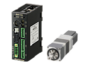
αSTEP AR Series FLEX DC Power Supply Input Built-In Controller Type > List of Product > ARM24SMK-H100+ARD-KD+CC030VA2FB2
- Accessory
- Motor: Varistor
Control Circuit: Power Supply Input Terminal Connector(CN1), Sensor Signal Connector(CN5), Input Signal Connector(CN8), Output Signal Connector(CN9)
- Safety Standards
-

| Product Type | Product Name | Product Leadtime | Unit Price(INR) | |
|---|---|---|---|---|
| Motor | ARM24SMK-H100 | 60 Working Days (Dispatch) | 66,667 | |
| Control Circuit | ARD-KD | 60 Working Days (Dispatch) | 33,000 | |
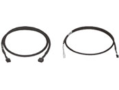
| Connection Cable | CC030VA2FB2 | 60 Working Days (Dispatch) | 5,867 |
Delivery date depends on products qty. Product price only. Dispatch from Bangalore Headquarter. Please contact ORIENTAL MOTOR (INDIA) PVT.LTD.
●Production Information
Product to be discontinued (Order deadline, 31/Jan/2025)
| Frame Size | 30 mm |
|---|---|
| Type | Harmonic Geared Type |
| Shaft Type | Single Shaft |
| Electromagnetic Brake | With |
| Cable | 3 m |
| Driver Type | Built-in Controller Type |
| Maximum Holding Torque | 2.4 N·m |
| Rotor Inertia J | 19×10^-7 kg·m^2 |
| Speed Range | 0 to 35 r/min |
| Gear Ratio | 100 |
| Resolution Setting: 1000 P/R | 0.0036 º/Pulse |
| Rated Torque | 2.4 N·m |
| Lost Motion (Load Torque) | 1.5 arcmin or less(±0.12 N·m) |
| Power Supply Input Voltage | 24 VDC |
| Power Supply Input Permissible Voltage Range | ±5% |
| Power Supply Input Current | 1.3 A |
| Electromagnetic Brake Type | Power off activated type |
| Electromagnetic Brake Power Supply | 24 VDC±5% 0.05 A ※1 |
| CE Marking | affixed |
| Number of Data-Select Positioning | 64 points |
| Positioning Operations | Single-Motion Operation: ○ Linked Operation: ○ Sequential Operation: ○ Direct Operation: ○ Push-Motion Operation: ○ |
| Continuous Operation | ○ |
| Return-To-Mechanical Home Operation | ○ |
| Return-To-Electrical Home Operation | ○ |
| Push Motion Return-To-Home Operation | ○ |
| Absolute System | ○ |
| Monitoring Function (Feedback position) | ○ |
| Teaching Pendant | OPX-2A |
| Data Setting Software | MEXE02 |
| Mass: Motor | 0.3 kg |
| Mass: Control Circuit | 0.17 kg |
- ●Maximum Instantaneous Torque: For the geared motor output torque, refer to the Speed – Torque Characteristics.
※1 For the electromagnetic brake type products, 24 VDC ±4% specification applies if the wiring between the motor and driver is extended to a distance from 20 to 30 m using a cable.
●The rotor inertia represents the inertia of the harmonic gear converted to motor shaft values.
The link of Web2CAD site can be used for 3D CAD data downloading as well. For more details, please click here.
| 2D-CAD | Motor | B1175.dxf |
|---|---|---|
| Control Circuit | B711.dxf | |
| 3D-CAD | Motor(STEP) | B1175.zip |
| Control Circuit(STEP) | B711.zip | |
| 3D-CAD(web2CAD) | Motor | to web2CAD site |
| Control Circuit | to web2CAD site | |
| Document | APPENDIX UL Standards for AR Series | HM-60116E.pdf |
| UL Certification(Circuit) | UL_E171462V4S6.pdf | |
| CE Declaration of Conformity | CE-6047.pdf | |
| Catalogue | Hybrid Control System αSTEP AR Series | AR Series_082019.pdf |
| Operating Manual | AR Series/Motorized actuator equipped the AR Series AC power input/DC power input Built-in Controller Type | HM-60340E.pdf |
| Data Setter OPX-2A AR Series Built-in Controller | HM-60219E.pdf | |
| Network converter CC-Link compatible NETC01-CC USER MANUAL | HM-60089E.pdf | |
| Network converter CC-Link Ver.2 compatible NETC02-CC USER MANUAL | HM-60305E.pdf | |
| Network converter MECHATROLINK-II compatible NETC01-M2 USER MANUAL | HM-60091E.pdf | |
| Network converter MECHATROLINK-III compatible NETC01-M3 USER MANUAL | HM-60093E.pdf | |
| Network converter EtherCAT compatible NETC01-ECT USER MANUAL | HM-60301E.pdf |
| Dimension |
|---|
|
Motor Control Circuit Cable |
| Characteristics Diagram |
|---|
|
Speed – Torque Load Torque – Driver Input Current |
| Other specifications |
|---|
|
Other specifications |