


The specialist of small precision motors - ORIENTAL MOTOR (INDIA) > Technical Support > Technical Question 3
|
|||
Mr. Vex:Dear Miss Ori, a customer ask me about pulse input signals. Can 24V pulse signals be used for stepping motor driver? I thought pulse signals only be used for 5V?
Miss Ori: Well, before i explain voltage of pulse signals. I will explain the basic pulse signal specifications in the 2004/2005 general catalogue.
 This drawing explains a pulse signal width, voltage level and pulse rising and falling edge widths. As long as pulse signals can satisfy this condition, they can be used for a stepping motor driver. Mr. Vex: That is right. I did not realize it even though i often looked at it. However, this drawing does not indicate the voltage.
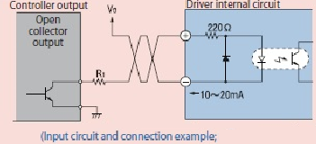
Oh, i understand this diagram!. This is a diagram that shows the input circuit using photocoupler being connected to the open collector output, isn't it ? It is also used for non-contact type AC speed control pack, right? Miss Ori: That' right. This shows an example of connection between 5 phases stepping motor RK Series driver and controller. CW/CCW pulse input signal area uses the photocoupler input method.
Photocouplers are an electronic components that relay electrical signals as light. They are electronically insulated on the input and outputs sides, so noise has little effect on them. A point to bear in mind is there is limitation of allowable current.
The pulse input terminal of RK Series requires 10mA to 20mA of electric current as indicated in this drawing. Whereas 5V pulse signal that you talked about can be connected directly to the driver without attaching a resistor (R1).
Mr. Vex: Overrun varies by the motor type?
Miss. Ori: Yes, reversible motor has approximately 5-6 revolutions for the over run.
Mr. Vex: Why does the reversible motor has smaller overrun than the induction motors.
Miss. Ori: Because the reversible motor has a built-in simple brake system, which enhances instant switching of rotating direction. That's is why it has smaller over turn compared to the induction motor.
Mr. Vex: If this is the case, when will the resistor (R1) be used?.
Miss. Ori: This resistor(R1) is necessary when connecting V0 more than 5V. As for 24V that the customer asked you about it is to be connected to the resistor with electric current value flowing in the photo coupler set between 10mA to 20 mA.
Mr. Vex:Well... How can i determine the value of the resistance?
Miss. Ori:For example , you can use this formula to calculate the resistance value in the case of 15mA.
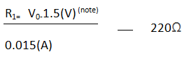 (note) for voltage drop for photocouple
Mr. Vex:This formula uses Ohm's laws, doesn't it?
Miss. Ori: You are right. Do remember it. What i explained so far is all written in the specification. You can study that.
Mr. Vex:It is difficult as there are many restrictions, aren't it?
Miss. Ori: I dont think so. You can rest assured that Oriental Motor's EMP400 and SG8030J controllers can be used without worrying about restrictions.
Besides, do you know there are 1-pulse and 2-pulse input modes depending on drivers functions, Vex?
Mr. Vex:2-pulse mode seems to have higher efficiency than 1-pulse mode. What are the differences?
Miss. Ori: It is not the case of which is better. The 1-pulse input mode uses the pulse signal and rotational direction signal, while the 2-pulse input mode uses the CW input for the CW direction and the CCW input for the CCW direction.

Mr. Vex:I see. Now i understand better.
Thank you very much, Ms Ori. i can now explain with confidence. I will contact the customer right away.
|